This repository documents the assembly, build process, and programming of a 6 Degrees of Freedom (6-DOF) robotic arm. The core software is now fully functional, allowing precise multi-axis control via joystick inputs.
📖 Full Doxygen Documentation: Click here to see
About the Project
The 3D printed parts are based on an excellent open-source model found on MakerWorld. To better understand the kinematics and prepare for the programming phase, I imported and fully assembled the components in Autodesk Fusion 360, where I also conducted a motion study.
Motion Study & Kinematics
Before starting the physical assembly, I validated the joint limits and basic movements using a Motion Study in Fusion 360. This ensures the mechanical design can achieve the required range of motion without collisions.
Current Status
- 3D printing of mechanical components.
- Virtual assembly in Fusion 360 & Kinematic simulation.
- Physical mechanical assembly and wiring.
- Core control code written and tested (ESP32 + PCA9685).
- Pending: Design and 3D print a custom enclosure to route cables and house the control electronics cleanly.
- Pending: Implement Inverse Kinematics (IK) math models.
Hardware (Bill of Materials)
- 3D Printed Parts: PLA/PETG (30% infill recommended for rigidity)
- Actuators: 3 x MG995 (180-degree) & 3 x MG90 MICRO
- Microcontroller: ESP32 Development Board
- Servo Controller: I2C PCA9685
- Position Control: 3 x XY Joystick Modules
Hardware Schematic
Software
The control software is written in C++ using PlatformIO/Arduino framework. It utilizes the Adafruit_PWMServoDriver library to offload PWM generation to the PCA9685 module over I2C. The current logic features a robust incremental movement system with adjustable speeds, hardware constraint mapping, and joystick deadzones to prevent jittering.
Hardware Challenges & Lessons Learned
The 360° vs. 180° Servo Motor Issue
During the initial prototyping and testing phase of the robotic arm, an unexpected behavior was observed: the joints would rotate continuously at varying speeds instead of holding a specific targeted angle. When the joystick was released to its center position, the motors would not stop accurately.
The Root Cause: The issue was traced back to the hardware type. The project inadvertently used 360-degree continuous rotation servos (MG996R 360°) instead of 180-degree positional servos. Because it was difficult to source the 180° variant of the MG996R locally, I pivoted to the MG995 model.
The fundamental difference lies in the internal feedback loop:
- Standard 180° Servo (MG995): Contains an internal potentiometer. The ESP32 PWM signal dictates the absolute position (e.g., go to 90° and lock there). This is mandatory for a robotic arm to hold objects against gravity.
- Continuous 360° Servo: The potentiometer is removed or replaced with fixed resistors. The PWM signal dictates speed and direction instead of position. Thus, a "center" signal might cause a slow drift, and the system has no way of knowing the physical angle of the arm.
The Solution: All base actuators were audited and replaced with true 180-degree MG995 positional servos. This hardware correction, combined with an incremental control logic in the ESP32 code, allowed the robotic arm to accurately track inputs and firmly hold its position when idle.
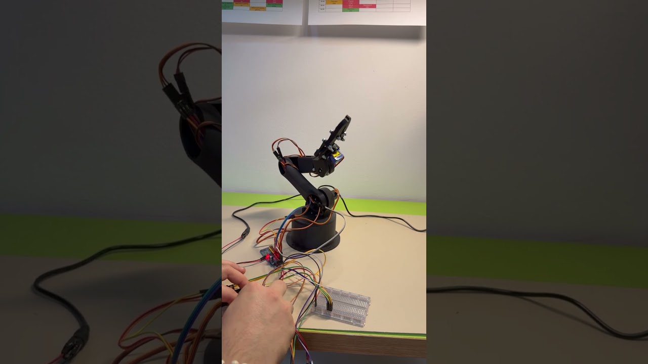
Future Plans: Electronics Enclosure
With the mechanical and software phases functioning perfectly, the current wiring setup is exposed. The next immediate step is to design a sleek, custom 3D printed enclosure in Fusion 360 to house the ESP32, the PCA9685 driver, the power distribution board, and the joysticks, transforming the prototype into a clean, finished product.