Full Doxygen Documentation: Click here to see it


Bill of Materials (BOM)
| Item / Component | Qty | Specifications / Model | Role in Project |
|---|---|---|---|
| Microcontroller | 1 | ESP32 Development Board | Main brain, Wi-Fi connectivity, and UI rendering. |
| Display | 1 | 1.69" IPS LCD Module | ST7789 driver, 240x280 resolution, SPI interface. |
| **Sensor** | 1 | DHT11 Module | Temperature and humidity reading (3-pin variant). |
| **Relay** | 1 | CW-020 5V Module | Low-level trigger; actuates the boiler's dry contact. |
| **Wiring** | Set | Jumper Wires (Dupont) | For connections between modules. |
| **Power Supply** | 1 | 5V Power Source (USB) | Powers the ESP32, which in turn provides 3.3V to the peripherals. |
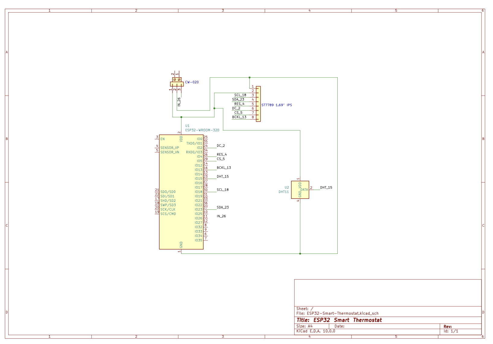
Hardware Schematic
The Build Process & Engineering Journey
Building this thermostat wasn't just about putting parts together; it involved solving real hardware and software constraints. Here is how the project evolved:
Phase 1: Breadboard Prototyping & Sensor Logic
The project started on a messy breadboard. The primary goal was to establish reliable communication between the ESP32, the DHT11 sensor, and the Blynk IoT cloud.
- Challenge: The DHT11 sensor reading blocked the main loop.
- Solution: Implemented BlynkTimer to read the sensor asynchronously every 2 seconds without halting the microcontroller.
Phase 2: Designing the Neumorphic UI & Beating RAM Limits
I wanted a premium, "Frosted Glass" UI similar to modern smart home hubs (like Ecobee).
- Challenge: Drawing complex graphics and clearing the screen (fillScreen) on an IPS display caused severe flickering. Attempting to use a full RAM Sprite (off-screen buffer) resulted in static/memory corruption because the ESP32 didn't have the contiguous ~134KB of free RAM required while running WiFi cryptography in the background.
- Solution: I engineered a State-Tracking System. The display now only redraws specific elements if and only if the temperature, humidity, or setpoint changes. Furthermore, to achieve the "transparent" text effect without RAM-heavy sprites, I dynamically matched the text background color to the underlying frosted glass circle color.
Phase 3: Hardware Actuation & Hysteresis
Connecting the 5V CW-020 relay to safely control a boiler's dry contact.
- Challenge: Preventing "short-cycling" (the boiler turning on/off rapidly when the room temperature hovers exactly around the target).
- Solution: Programmed a 0.5°C hysteresis logic. If the target is 22°C, heating starts at 21.5°C and stops at 22.5°C, protecting the physical hardware from premature wear.
Phase 4: PCB Design & Professional Workflows
Transitioned from the breadboard to a formal schematic using KiCad to document the exact pinouts, logic-level power distribution, and safe relay wiring for future PCB fabrication. The codebase was also migrated from Arduino IDE to Visual Studio Code (C++), complete with automated Doxygen documentation for clean, maintainable architecture.
⚠️ Critical Display Configuration (TFT_eSPI)
Important: If you simply compile the main.cpp file, the display will remain blank (white screen). The TFT_eSPI library requires hardware-specific configurations to know which display driver and pins you are using.
You need to inject the display settings directly into your platformio.ini file using build flags. Add the following to your platformio.ini:
```ini build_flags = -D USER_SETUP_LOADED=1 -D ST7789_DRIVER=1 -D TFT_WIDTH=240 -D TFT_HEIGHT=280 -D TFT_MOSI=23 -D TFT_SCLK=18 -D TFT_CS=5 -D TFT_DC=2 -D TFT_RST=4 -D LOAD_GLCD=1 -D LOAD_FONT2=1 -D LOAD_FONT4=1 -D LOAD_FONT6=1 -D SPI_FREQUENCY=27000000